NorthWest Engineering Service, Inc.
Semiconductor fabrication facilities (fabs) require strict environmental control to ensure high yield and reliable tool performance. HVAC maintenance and semiconductor tool balancing are essential practices that affect all fab levels. Poor airflow, pressure imbalances, or neglected equipment can result in contamination, process instability, or tool downtime. A single advanced wafer can be worth up to $20,000, so maintaining precise environmental standards is directly tied to the fab’s profitability. The following breakdown examines how HVAC maintenance and tool balancing provide distinct benefits across each floor of a semiconductor fab.
Floor 1: Interstitial Space
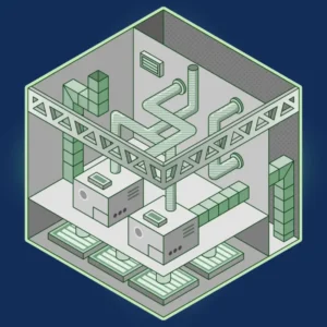 The interstitial space above the cleanroom houses fan filter units (FFUs), HEPA/ULPA filters, and associated ductwork responsible for supplying clean, conditioned air downward into the cleanroom. It also plays a key role in maintaining the pressure cascade that isolates clean areas from less-controlled adjacent spaces. The performance of this floor directly influences air cleanliness and pressure control in the cleanroom below.
Regular maintenance and test-and-balance (TAB) procedures are critical in this area. As indicated by Plant Engineering, ensuring airflow uniformity through the ceiling filter system supports compliance with ISO 14644-1:2015 cleanliness standards, typically ISO Classes 3-5 for cleanrooms. Filter replacement and damper calibration prevent airflow stagnation or turbulence, which can lead to particle accumulation. Properly maintained fan units and filters also ensure pressure differentials are maintained according to specification, reducing the risk of contamination backflow. Additionally, clean filters and optimized fan operation improve energy efficiency by lowering static pressure losses.
Floor 2: Cleanroom
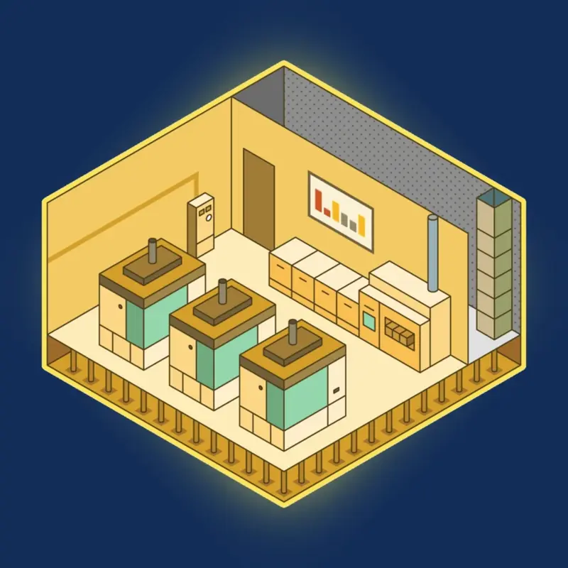 The cleanroom is where wafer processing occurs, making it the most sensitive zone in the fab. It must strictly control temperature, humidity, and airborne particle concentration. Cleanroom air is delivered from the above interstitial space and exhausted or returned via floor-level vents.
Maintenance of HEPA/ULPA filters, ceiling FFUs, and air handling components is essential for controlling airborne particles. Balanced laminar airflow is required to prevent particle deposition on wafers and tooling surfaces. Temperature is typically held within ±0.1–0.2 °C, and humidity within ±1% RH, particularly in photolithography and etch areas where slight deviations can affect process uniformity (Semiconductor Digest). Stable environmental conditions reduce variability in photoresist behavior, minimize defects, and ensure repeatability between process runs. Routine cleanroom performance testing, including airflow velocity, pressure differential, and particle count measurements, is critical to verify environmental control and ensure compliance with ISO classification standards.
Floor 3: Sub-Fab
 The sub-fab is the bustling underbelly of the fab, a floor packed with support equipment (vacuum pumps, abatement systems, gas cabinets, chemical delivery units, power distribution, and more) that enable the cleanroom tools to run. This area generates significant heat and requires robust ventilation to maintain safe operating conditions.
Every process tool in the cleanroom usually has one or more exhaust connections that remove fumes, byproducts, and heat. In the sub-fab, these exhaust lines from multiple tools often converge into common ducts. Properly balancing these exhaust flows is both an art and a science. Technicians adjust dampers and valves so that each tool’s exhaust is at the correct flow rate – enough to safely capture hazardous fumes and maintain stable pressure at the tool, but not so much that it starves other tools or wastes energy. In large fabs, dozens of tools might share an exhaust header, each finely balanced on a system running near maximum capacity. Even minor airflow inaccuracies can create crosstalk—pressure fluctuations that disturb neighboring tools, so you need highly specialized TAB technicians to balance these systems.
As our Company President, Tom Prevish, put it, “An entire line can be brought down by a tap of the hammer that moves the damper 10% too far or a wayward bump of the elbow while crawling in and among the utilities” (Plant Engineering).
Floor 4: Utility Room
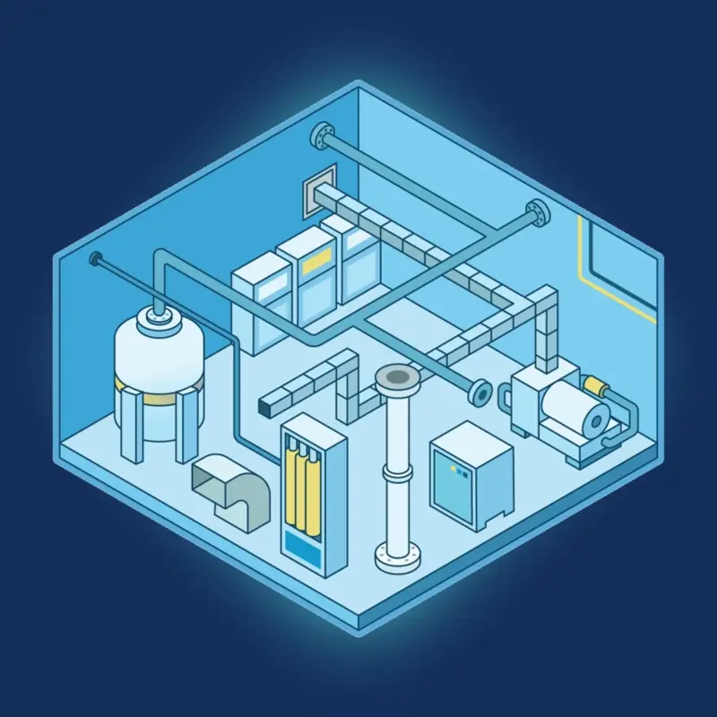
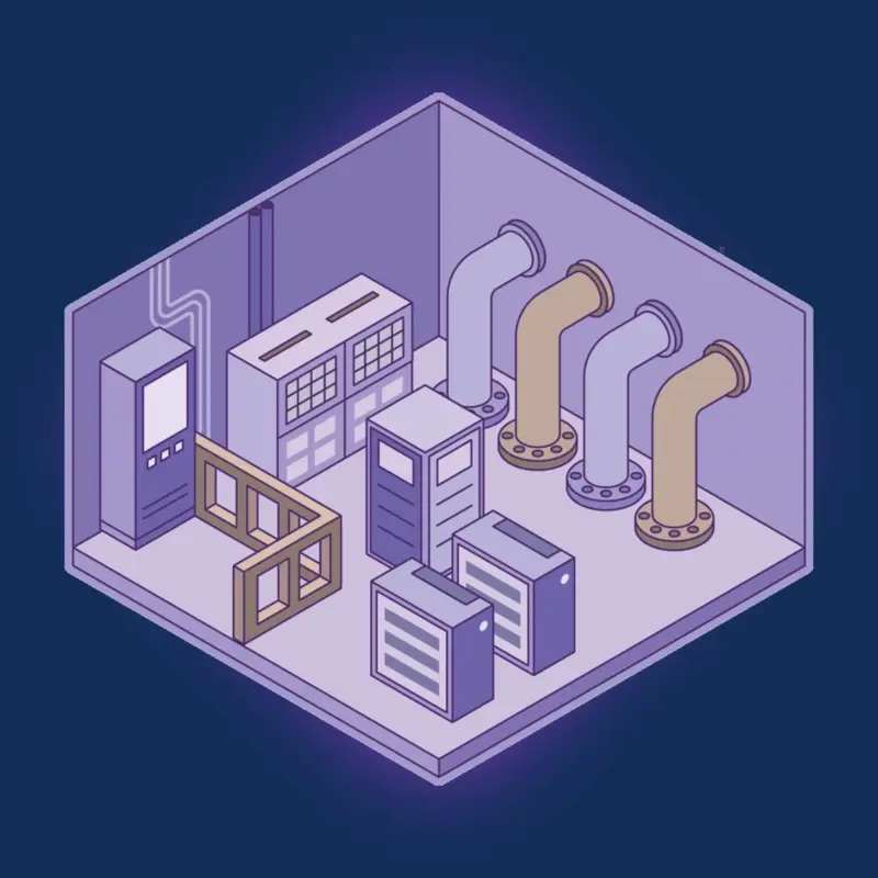 The utility room or mechanical plant supports the entire fab’s infrastructure, including chilled water systems, boilers, air handling units (AHUs), compressed air, and other critical utilities. This equipment delivers the heating, cooling, humidity control, and airflow required by all other fab floors.
Preventive maintenance of HVAC systems here ensures uninterrupted delivery of climate control services across the fab. Failures in these systems can result in widespread environmental instability and downtime. Industry research shows that one hour of planned maintenance can save 3–4 hours of unplanned downtime in semiconductor fabs (McKinsey & Company). It’s much better (and cheaper) to replace a failing bearing on your schedule than to have an air handler seize up during a production run.
Additionally, compliance with standards such as ASHRAE guidelines, local building codes, and environmental regulations often requires documented maintenance. A well-run utility room with clear maintenance logs makes audits uneventful. For instance, emission control devices like VOC absorbers or waste treatment systems tied to HVAC drains may require periodic checks to remain compliant.
Conclusion
HVAC maintenance and tool balancing across all fab floors directly support product yield, equipment uptime, and fab safety. Consistent airflow, stable environmental conditions, and precise pressure control are foundational to reducing defects and improving energy efficiency. Well-maintained systems also ensure compliance with cleanroom standards and safety regulations, making these practices essential to the long-term success of semiconductor manufacturing.
 NWESI’s STEP (Semiconductor Tool Exhaust Performance) program enhances these efforts by providing tailored TAB services that optimize airflow and tool performance. With cleanroom expertise and real-time exhaust tracking, STEP helps fabs boost uptime, efficiency, and long-term reliability.